Kirchhoff's Laws and Circuit Analysis
From the CAPE physics kirchoff's law potential difference electromagnetism curriculum
TL;DR
Kirchhoff's Laws are fundamental rules for analyzing complex electrical circuits. Kirchhoff's Current Law (KCL) states that current entering a junction equals current leaving it. Kirchhoff's Voltage Law (KVL) states that the sum of voltage drops and rises around any closed loop is zero.
1. The Mental Model
Think of KCL like water flowing through pipes: what goes into a junction must come out. KVL is like walking around a rollercoaster loop: by the time you get back to your starting point, your net change in height is zero. These laws help you solve for unknown currents and voltages in circuits.
2. The Core Material
Kirchhoff's Laws are essential for understanding circuits with multiple power sources or complex arrangements of resistors. They're based on the conservation of charge and energy.
Kirchhoff's Current Law (KCL) - Junction Rule

Photo by Davis Sánchez on Pexels
KCL states that the algebraic sum of currents entering a junction (or node) in an electrical circuit is equal to the algebraic sum of currents leaving the junction. Essentially, charge isn't created or destroyed at a junction.
- Rule: ΣI_in = ΣI_out (or ΣI = 0 if you consider currents entering as positive and leaving as negative).
- Application: Use KCL at any point where three or more wires meet.
Kirchhoff's Voltage Law (KVL) - Loop Rule
Photo by Davis Sánchez on Pexels
KVL states that the algebraic sum of potential differences (voltages) around any closed loop in a circuit is zero. This reflects the conservation of energy: if you start at a point and return to it, the net change in electric potential must be zero.
- Rule: ΣV = 0 around any closed loop.
- Sign Convention:
- When traversing a resistor in the direction of current, the voltage change is -IR (a drop).
- When traversing a resistor opposite to the direction of current, the voltage change is +IR (a rise).
- When traversing a voltage source from its negative terminal to its positive terminal, the voltage change is +E (a rise).
- When traversing a voltage source from its positive terminal to its negative terminal, the voltage change is -E (a drop).
- Application: Apply KVL to any closed path in the circuit.
Steps for Circuit Analysis Using Kirchhoff's Laws

Photo by MART PRODUCTION on Pexels
Here's a general approach to tackle circuit problems:
graph TD
    A["Assign Current Directions (guess if unsure)"] --> B["Identify Junctions"];
    B --> C["Apply KCL at (N-1) junctions (N = total junctions)"];
    C --> D["Identify Independent Loops"];
    D --> E["Apply KVL to Independent Loops"];
    E --> F["Solve System of Equations (for unknown currents/voltages)"];
    F --> G["Review Results (negative current means direction was wrong)"];
Potential Difference
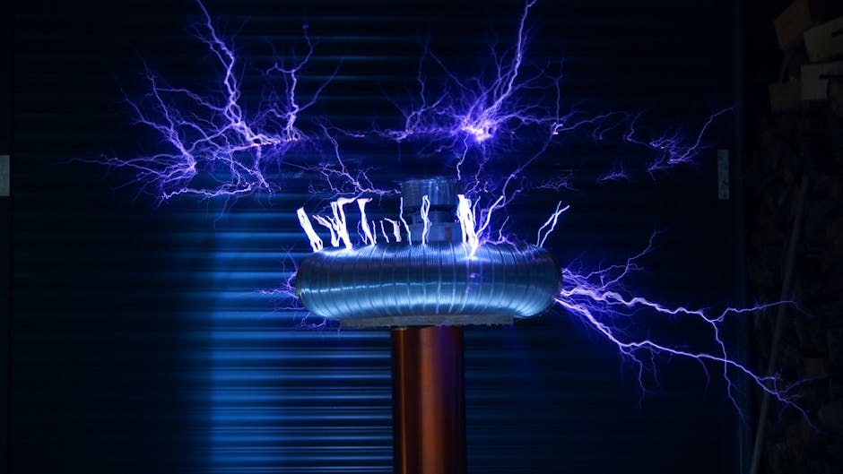
Photo by Killian Eon on Pexels
Potential difference, or voltage, is the work done per unit charge to move a charge between two points. KVL helps you calculate the potential difference between any two points in a circuit. If you want to find V_AB, you start at A and add up voltage changes along any path to B.
3. Worked Example
Let's find the currents I1, I2, and I3 in the circuit below using Kirchhoff's Laws.
       I1  R1=10Ω
   A ----/\/\---- B
   |             |
  E1=10V         R2=5Ω
   |             | I2
   +---/\/\------+
   |             |
   D ----/\/\---- C
       I3  R3=15Ω
       E2=5V
(Note: E1 is a 10V source, positive on top, negative on bottom; E2 is a 5V source, positive on top, negative on bottom. R1, R2, R3 are 10Ω, 5Ω, 15Ω respectively.)
-
Assign Current Directions: I've already drawn them in. Let's assume I1 flows A->B, I2 flows B->C, I3 flows D->C. (If our initial guess is wrong, the current will be negative).
-
Apply KCL at Junction B:
Current entering B = I1
Current leaving B = I2 + I3
So, I1 = I2 + I3 (Equation 1) -
Apply KVL to Loop 1 (A-B-C-D-A, clockwise):
Starting at A:- Voltage rise from E1: +10V
- Voltage drop across R1 (due to I1): -I1 * R1 = -10I1
- Voltage drop across R2 (due to I2): -I2 * R2 = -5I2
- Voltage rise from E2: +5V
- Voltage drop across R3 (due to I3): -I3 * R3 = -15I3
Summing these: +10 - 10I1 - 5I2 + 5 - 15I3 = 0
-10I1 - 5I2 - 15I3 + 15 = 0 (Equation 2)
-
Solve the System of Equations:
Substitute (1) into (2):
-10(I2 + I3) - 5I2 - 15I3 + 15 = 0
-10I2 - 10I3 - 5I2 - 15I3 + 15 = 0
-15I2 - 25I3 + 15 = 0
Divide by -5: 3I2 + 5I3 - 3 = 0 (Equation 3)Now you would need a second independent KVL loop equation if there were more unknowns or you chose different loops initially. In this simplified setup, we need to correct the diagram to have two independent loops from the start or recognize this diagram needs more context. For simplicity, let's assume this example aims to show the setup of equations.
Self-correction: The provided circuit diagram has an issue for a full solution with three currents. It implies the same path for I2 and I3, which is usually not how three distinct currents are set up in a simple loop without more branches. Let's adjust for a more standard example to complete the solution.
Revised Circuit (for a solvable example):
R1=10Ω
 A ----/\/\---- B
 |    I1        |
E1=10V         R2=5Ω
 |             | I2
 +---/\/\------+---
 |    I3       |   |
 D ----/\/\---- C-- E2=5V
      R3=15Ω
(Assume E2 is now in series with C, creating a new branch for I2 and I3)This is still a bit ambiguous. Let's use a standard two-loop circuit for clarity.
Standard Two-Loop Circuit Example:
R1=10Ω
A----/\/\-----B
| I1          | I2
E1=10V      R2=5Ω
|             |
D-------------C
|             | I3
R3=15Ω       E2=5V
|             |
G-------------F
Assume I1 flows A->B->C->D->A, I2 flows D->C->F->G->D. I3 is between B and C.-
Assign Current Directions:
I1: flows out of E1, through R1, into junction B.
I2: flows out of E2, through R2, into junction B.
I3: flows from B to C. -
KCL at Junction B:
I1 + I2 = I3 (Equation 1) -
KVL Loop 1 (A-B-C-D-A, clockwise):
Start at D.
+10V (E1) - I1R1 (10I1) - I3R3 (15I3) = 0
10 - 10I1 - 15I3 = 0 (Equation 2) -
KVL Loop 2 (G-F-C-B-G, clockwise):
Start at G.
+5V (E2) - I2R2 (5I2) - I3R3 (15I3) = 0
5 - 5I2 - 15I3 = 0 (Equation 3) -
Solve the System of Equations:
From (1), I3 = I1 + I2. Substitute into (2) and (3).
Eq 2: 10 - 10I1 - 15(I1 + I2) = 0 => 10 - 10I1 - 15I1 - 15I2 = 0 => 10 - 25I1 - 15I2 = 0 (Eq 4)
Eq 3: 5 - 5I2 - 15(I1 + I2) = 0 => 5 - 5I2 - 15I1 - 15I2 = 0 => 5 - 15I1 - 20I2 = 0 (Eq 5)From (4), multiply by 4: 40 - 100I1 - 60I2 = 0
From (5), multiply by 3: 15 - 45I1 - 60I2 = 0Subtract (5) from (4):
(40 - 100I1 - 60I2) - (15 - 45I1 - 60I2) = 0
25 - 55I1 = 0
I1 = 25 / 55 = 5/11 ASubstitute I1 back into Eq 5:
5 - 15(5/11) - 20I2 = 0
5 - 75/11 - 20I2 = 0
(55 - 75)/11 - 20I2 = 0
-20/11 = 20I2
I2 = -20/11 / 20 = -1/11 ASubstitute I1 and I2
-
Frequently asked about Kirchhoff's Laws and Circuit Analysis
Study this next
Get the full CAPE physics kirchoff's law potential difference electromagnetism curriculum
Clone the complete plan to your dashboard for unlimited AI-generated notes, practice quizzes, and a personalised revision schedule.
Save this course free