AC Circuit Analysis
From the Applied electricity curriculum
TL;DR
AC circuit analysis involves understanding how components like resistors, inductors, and capacitors behave with alternating current. We use phasors and complex numbers to represent these quantities, making calculations similar to DC circuits. Impedance is the AC equivalent of resistance, accounting for magnitude and phase shift.
1. The Mental Model
Imagine AC electricity as a wave, constantly changing direction and magnitude. We can "freeze" this wave at a certain point in its cycle and represent it as a rotating arrow (a phasor), which helps us visualize how different components in a circuit affect its direction and length.
2. The Core Material
In AC circuits, voltage and current aren't always "in sync" like they are in DC. This "phase shift" is crucial.
Resistors in AC
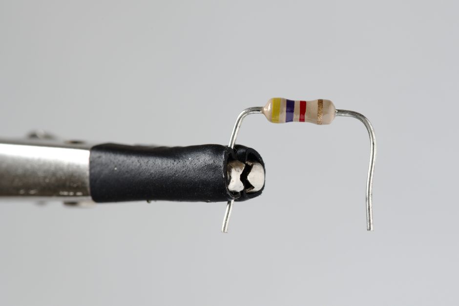
Photo by Zacharias Korsalka on Pexels
Resistors behave the same in AC as they do in DC. The current and voltage across a resistor are always in phase (they peak and cross zero at the same time).
* Ohm's Law: V = I * R
* Impedance (Z): For a resistor, Z = R (a purely real number).
Inductors in AC

Photo by Nothing Ahead on Pexels
Inductors resist changes in current. In an AC circuit, this means they constantly oppose the changing current. The voltage across an inductor leads the current by 90 degrees (meaning the voltage peaks before the current does).
* Inductive Reactance (X_L): This is the opposition to current flow offered by an inductor in an AC circuit.
* X_L = 2 * π * f * L
* Where:
* f is the frequency in Hertz (Hz)
* L is the inductance in Henrys (H)
* Impedance (Z): For an ideal inductor, Z = j * X_L (a purely imaginary number, 'j' represents the 90-degree phase shift).
Capacitors in AC
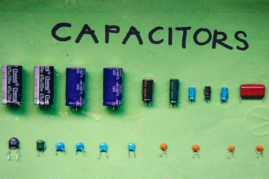
Photo by Nothing Ahead on Pexels
Capacitors store charge and resist changes in voltage. In an AC circuit, they constantly charge and discharge. The current through a capacitor leads the voltage by 90 degrees (meaning the current peaks before the voltage does).
* Capacitive Reactance (X_C): This is the opposition to current flow offered by a capacitor in an AC circuit.
* X_C = 1 / (2 * π * f * C)
* Where:
* f is the frequency in Hertz (Hz)
* C is the capacitance in Farads (F)
* Impedance (Z): For an ideal capacitor, Z = -j * X_C (a purely imaginary number with a negative sign, representing the -90-degree phase shift).
Impedance (Z) and Complex Numbers

Photo by Vitaly Gariev on Pexels
Impedance (Z) is the total opposition to current flow in an AC circuit. It combines resistance (R) and reactance (X_L or X_C) into a single complex number.
* Series RLC Circuit Impedance: Z = R + j(X_L - X_C)
* The real part (R) is resistance.
* The imaginary part (X_L - X_C) is the total reactance (X).
* Magnitude of Impedance: |Z| = sqrt(R^2 + X^2)
* Phase Angle (θ): θ = arctan(X / R)
* This angle tells you the phase difference between the total voltage and total current in the circuit.
Phasor Diagrams
Phasor diagrams are visual tools that represent AC voltages and currents as rotating vectors (phasors). They help you see the phase relationships between different quantities.
graph TD
    AC_Voltage_Source["AC Voltage Source (V)"] --> Resistor["Resistor (R)"]
    AC_Voltage_Source --> Inductor["Inductor (L)"]
    AC_Voltage_Source --> Capacitor["Capacitor (C)"]

    Resistor --> Current_in_Phase["Current (I) in phase with Voltage (V)"]
    Inductor --> Voltage_Leads_Current["Voltage (V_L) leads Current (I) by 90°"]
    Capacitor --> Current_Leads_Voltage["Current (I) leads Voltage (V_C) by 90°"]
Power in AC Circuits
- Real Power (P): The actual power dissipated by the resistance in the circuit, measured in Watts (W).
- P = V * I * cos(θ) = I^2 * R
- Reactive Power (Q): Power exchanged between the source and the reactive components (inductors and capacitors), not dissipated. Measured in Volt-Ampere Reactive (VAR).
- Q = V * I * sin(θ) = I^2 * X
- Apparent Power (S): The total power supplied by the source, measured in Volt-Amperes (VA).
- S = V * I = sqrt(P^2 + Q^2)
- S = |V| * |I| (magnitude of total voltage times magnitude of total current)
- Power Factor (PF): cos(θ) = P / S. This tells you how effectively the apparent power is being converted into real power. A PF closer to 1 is better.
3. Worked Example
Let's analyze a series RLC circuit.
A series circuit has:
* Resistor (R) = 30 Ω
* Inductor (L) = 40 mH (0.04 H)
* Capacitor (C) = 50 µF (50 x 10^-6 F)
* AC Voltage Source: V = 120V (RMS) at f = 60 Hz
Step 1: Calculate Reactances
* Inductive Reactance (X_L):
* X_L = 2 * π * f * L = 2 * π * 60 Hz * 0.04 H
* X_L ≈ 15.08 Ω
* Capacitive Reactance (X_C):
* X_C = 1 / (2 * π * f * C) = 1 / (2 * π * 60 Hz * 50 x 10^-6 F)
* X_C ≈ 53.05 Ω
Step 2: Calculate Total Impedance (Z)
* Z = R + j(X_L - X_C)
* Z = 30 + j(15.08 - 53.05)
* Z = 30 - j37.97 Ω
Step 3: Calculate Magnitude of Impedance (|Z|)
* |Z| = sqrt(R^2 + X^2) = sqrt(30^2 + (-37.97)^2)
* |Z| = sqrt(900 + 1441.72) = sqrt(2341.72)
* |Z| ≈ 48.39 Ω
Step 4: Calculate Phase Angle (θ)
* θ = arctan(X / R) = arctan(-37.97 / 30)
* θ ≈ arctan(-1.2657)
* θ ≈ -51.7° (The negative sign indicates current leads voltage, as X_C > X_L, making the circuit capacitive overall)
Step 5: Calculate Total Current (I)
* I = V / |Z| = 120V / 48.39 Ω
* I ≈ 2.48 A (RMS)
4. Key Takeaways
- AC circuits introduce phase shifts between voltage and current due to inductors and capacitors.
- Inductors cause voltage to lead current, while capacitors cause current to lead voltage.
- Impedance (Z) is the complex AC equivalent of resistance, accounting for both magnitude and phase.
- Complex numbers simplify AC circuit calculations, allowing you to treat them like DC problems.
- The phase angle (θ) tells you the overall phase relationship between the total voltage and current.
- Power factor (PF) is important for understanding how efficiently power is used in an AC circuit.
Common Mistakes to Avoid:
- Forgetting frequency dependence: Reactance (X_L and X_C) directly depends on frequency, unlike resistance.
- Mixing up leading/lagging: Always remember which quantity (voltage or current) leads or lags for inductors and capacitors.
- Adding impedances like plain resistors: You must add impedances as complex numbers, not just their magnitudes.
- Ignoring RMS vs. Peak: Ensure you're using consistent values (RMS or peak) for voltage and current in calculations.
5. Now Try It
You have a parallel AC circuit with a 100 Ω resistor and a 200 mH inductor connected to a 240V, 50 Hz AC source.
1. Calculate the inductive reactance (X_L).
2. Calculate the impedance of the resistor (Z_R) and the inductor (Z_L).
3. Determine the total current drawn from the source and its phase angle relative to the source voltage.
Success looks like calculating X_L, expressing Z_R and Z_L as complex numbers, and then finding the total current and its phase angle (which will require combining parallel impedances).
Frequently asked about AC Circuit Analysis
Study this next
Get the full Applied electricity curriculum
Clone the complete plan to your dashboard for unlimited AI-generated notes, practice quizzes, and a personalised revision schedule.
Save this course free