DC Circuit Analysis Techniques
From the Applied electricity curriculum
TL;DR
You'll learn how to break down complex DC circuits into simpler parts to find unknown voltages and currents. We'll cover fundamental tools like Kirchhoff's Laws, Ohm's Law, and powerful methods like nodal and mesh analysis. Mastering these techniques lets you predict circuit behavior without building it physically.
1. The Mental Model
Imagine a water pipe system: voltage is like water pressure, and current is the water flow. Circuit analysis techniques are like having a map and tools to figure out how much pressure and flow are at different points, even in really complicated systems with many pipes and pumps.
2. The Core Material
When you're faced with a DC circuit, your goal is usually to find specific voltages or currents. Simple circuits can often be solved with Ohm's Law and series/parallel resistor combinations, but complex ones need more advanced techniques.
Kirchhoff's Laws: The Foundation
These two laws are the bedrock of all circuit analysis:
-
Kirchhoff's Current Law (KCL): What goes in must come out. At any junction (node) in a circuit, the total current entering that node must equal the total current leaving it. Think of it like a traffic intersection – the number of cars entering must equal the number of cars leaving. Mathematically, the algebraic sum of currents entering a node is zero.
- $\sum I_{in} = \sum I_{out}$
- Or, $\sum I_{node} = 0$ (assigning positive to currents leaving, or entering, consistently)
-
Kirchhoff's Voltage Law (KVL): The sum of all voltage drops and rises around any closed loop in a circuit must be zero. If you walk around a complete loop and measure every voltage change (battery voltage, voltage drop across a resistor), you'll end up back where you started with a net change of zero.
- $\sum V_{loop} = 0$
Ohm's Law: The Basic Relationship
You already know this one, but it's crucial for applying KVL and KCL:
* $V = IR$ (Voltage = Current × Resistance)
* $I = V/R$
* $R = V/I$
Series and Parallel Resistors: Simplification
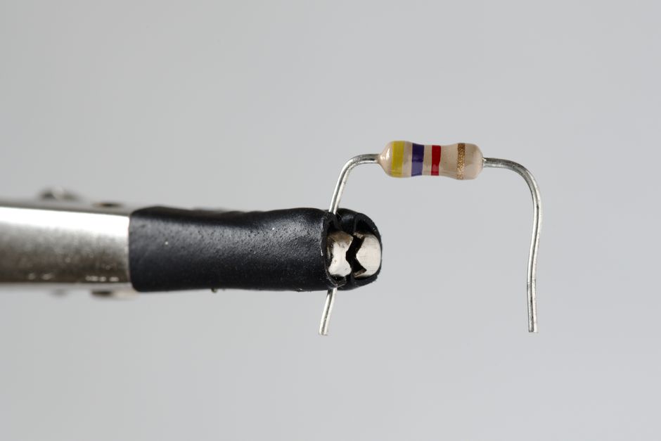
Photo by Zacharias Korsalka on Pexels
Before diving into complex methods, always look for ways to simplify.
- Series Resistors: If resistors are end-to-end and share the same current, their total resistance is the sum of individual resistances.
- $R_{total} = R_1 + R_2 + ... + R_n$
- Parallel Resistors: If resistors are connected across the same two points (sharing the same voltage), their equivalent resistance is found using the reciprocal formula.
- $1/R_{total} = 1/R_1 + 1/R_2 + ... + 1/R_n$
- For two resistors: $R_{total} = (R_1 \times R_2) / (R_1 + R_2)$
Nodal Analysis: Focusing on Voltages
Nodal analysis is powerful when you want to find node voltages. It uses KCL to write equations.
- Identify Nodes: Mark all the distinct connection points (nodes) in the circuit.
- Choose a Reference Node: Pick one node as your ground or reference node (usually the one with most connections, or the negative terminal of a voltage source). Its voltage is 0V.
- Assign Node Voltages: Assign unknown voltage variables ($V_A, V_B$, etc.) to all other non-reference nodes.
- Write KCL Equations: For each non-reference node, write a KCL equation assuming currents leave the node. Express these currents using Ohm's Law ($I = V/R$).
- Example: Current leaving node A towards node B is $(V_A - V_B) / R$.
- Current leaving node A towards ground (0V) is $(V_A - 0) / R = V_A / R$.
- Solve the System of Equations: You'll end up with a system of linear equations. Solve them simultaneously to find the unknown node voltages.
Mesh Analysis: Focusing on Currents
Mesh analysis is great when you want to find loop currents. It uses KVL to write equations. A "mesh" is a loop that does not contain any other loops within it.
- Identify Meshes: Determine the number of independent closed loops (meshes) in the circuit.
- Assign Mesh Currents: Assign a circulating current (e.g., $I_1, I_2$) to each mesh, usually in a clockwise direction.
- Write KVL Equations: For each mesh, apply KVL.
- If you pass through a resistor in the direction of your mesh current, it's a voltage drop ($I \times R$). If another mesh current also flows through that resistor in the opposite direction, subtract its contribution.
- If you pass through a voltage source from negative to positive, it's a voltage rise (positive value). If positive to negative, it's a voltage drop (negative value).
- Solve the System of Equations: Solve the resulting system of linear equations to find the unknown mesh currents. Once you have mesh currents, you can find any branch current or voltage.
Here's a flowchart to help you decide which method to use:
graph TD
    A["Start Analysis"] --> B{"Need all branch currents or specific voltages?"}
    B -- "All branch currents" --> C{"Circuit has many loops (meshes)?"}
    B -- "Specific node voltages" --> D{"Circuit has many nodes?"}

    C -- "Yes" --> E["Use Mesh Analysis (KVL)"]
    C -- "No / Few" --> F["Try KVL directly / Simplify"]

    D -- "Yes" --> G["Use Nodal Analysis (KCL)"]
    D -- "No / Few" --> H["Try KCL directly / Simplify"]

    E --> I["Solve system for mesh currents"]
    F --> I
    G --> I["Solve system for node voltages"]
    H --> I

    I --> J["Calculate desired values (V, I, P)"]
    J --> K["End Analysis"]
3. Worked Example
Let's find the voltage across R2 ($V_{R2}$) in the following circuit using Nodal Analysis.
Circuit:
A 10V source connected to a node (Node A).
From Node A:
- R1 (2 Ohms) connects to ground.
- R2 (4 Ohms) connects to Node B.
From Node B:
- R2 (4 Ohms) connects back to Node A.
- R3 (6 Ohms) connects to ground.
Nodes: Ground (0V), Node A, Node B.
- Reference Node: Ground (0V).
- Non-reference Nodes: $V_A$, $V_B$.
-
Identify $V_A$: Notice that Node A is directly connected to the positive terminal of the 10V source, whose negative terminal is at ground. Therefore, $V_A = 10V$. This simplifies things! We only need to find $V_B$.
-
Write KCL for Node B: Assume currents are leaving Node B.
- Current from B to A (through R2): $(V_B - V_A) / R2$
- Current from B to Ground (through R3): $(V_B - 0) / R3$
So, KCL at Node B:
$(V_B - V_A) / R2 + V_B / R3 = 0$ -
Substitute known values ($V_A=10V$, $R2=4\Omega$, $R3=6\Omega$):
$(V_B - 10) / 4 + V_B / 6 = 0$ -
Solve for $V_B$:
To clear denominators, multiply the entire equation by the least common multiple of 4 and 6, which is 12:
$12 \times [(V_B - 10) / 4] + 12 \times [V_B / 6] = 12 \times 0$
$3(V_B - 10) + 2V_B = 0$
$3V_B - 30 + 2V_B = 0$
$5V_B = 30$
$V_B = 6V$
Now we have $V_A = 10V$ and $V_B = 6V$.
Find $V_{R2}$: The voltage across R2 is the potential difference between Node A and Node B.
$V_{R2} = V_A - V_B = 10V - 6V = 4V$
4. Key Takeaways
- KCL and KVL are fundamental: Always start by understanding how these laws apply to your circuit.
- Simplify first: Look for series/parallel combinations before applying more complex methods.
- Nodal analysis for voltages: It's best when you need to find voltages at various points (nodes) in the circuit.
- Mesh analysis for currents: Use it when you need to find the currents flowing in different loops of the circuit.
- Choose wisely: The right technique simplifies the problem; the wrong one can make it harder.
- Practice makes perfect: The more you apply these methods, the more intuitive they become.
Common Mistakes to Avoid:
- Incorrectly assigning current directions: Be consistent (e.g., all currents leaving a node for KCL, or all clockwise for mesh currents).
- Algebraic errors: Solving systems of equations requires careful calculation.
- Forgetting voltage source polarities: Pay close attention to +/- signs when applying KVL.
- Misidentifying nodes or meshes: Ensure you've correctly defined all independent nodes or loops.
5. Now Try It
Consider a circuit with a 20V voltage source. The positive terminal is connected to Node 1. From Node 1, R1 (5 Ohms) connects to Node 2. Also from Node 1, R2 (10 Ohms) connects to ground. From Node 2, R3 (15 Ohms) connects to ground.
Your task is to use Nodal Analysis to find the voltage at Node 2 ($V_2$).
What to do:
1. Identify all nodes and choose a reference node (ground).
2. Determine any known node voltages.
3. Write the KCL equation for Node 2.
4. Solve the equation for $V_2$.
What success looks like: You should arrive at $V_2 = 12V$.
Frequently asked about DC Circuit Analysis Techniques
Study this next
Get the full Applied electricity curriculum
Clone the complete plan to your dashboard for unlimited AI-generated notes, practice quizzes, and a personalised revision schedule.
Save this course free