Ethernet Framing and Data Integrity
From the ITCTA curriculum
TL;DR
Ethernet framing is how data gets packaged for transmission across a local network, dividing information into specific sections for efficient delivery. Data integrity mechanisms, primarily the Frame Check Sequence (FCS), ensure that data isn't corrupted during its journey. Understanding these concepts helps you troubleshoot network issues and grasp the fundamentals of network communication.
1. The Mental Model
Think of Ethernet framing like putting a letter into an envelope. The "letter" is your data, and the "envelope" is the Ethernet frame, with specific spots for the sender's address, the receiver's address, and a stamp to make sure it arrived okay.
2. The Core Material
Ethernet framing defines the structure of data packets, called frames, that travel over an Ethernet network. Each part of the frame has a specific job to do.
Ethernet Frame Structure
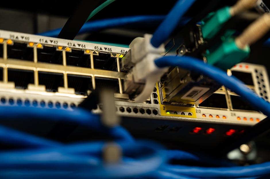
Photo by Brett Sayles on Pexels
An Ethernet frame is typically composed of several fields:
- Preamble (7 bytes): A sequence of alternating 1s and 0s (
10101010) that helps the receiving device synchronize its clock with the incoming data stream. - Start Frame Delimiter (SFD) (1 byte): The sequence
10101011marks the end of the preamble and the beginning of the actual frame data. - Destination MAC Address (6 bytes): Specifies the physical address of the receiving device.
- Source MAC Address (6 bytes): Specifies the physical address of the sending device.
- Type/Length (2 bytes):
- Type: If its value is 1536 (0x0600) or greater, it indicates the protocol type of the data payload (e.g., IP, ARP).
- Length: If its value is 1500 (0x05DC) or less, it indicates the length of the data payload in bytes.
- Data (Payload) (46-1500 bytes): The actual data being transmitted, such as an IP packet. If the data is less than 46 bytes, padding bytes are added to meet the minimum frame size.
- Frame Check Sequence (FCS) (4 bytes): This is where data integrity comes in. It's a checksum calculated by the sender based on the entire frame (from Destination MAC to Data). The receiver recalculates the FCS and compares it with the received FCS to detect errors.
Here's a visual of the Ethernet frame structure:
graph LR
    A["Preamble (7 bytes)"] --> B["SFD (1 byte)"]
    B --> C["Destination MAC (6 bytes)"]
    C --> D["Source MAC (6 bytes)"]
    D --> E["Type/Length (2 bytes)"]
    E --> F["Data (Payload) (46-1500 bytes)"]
    F --> G["FCS (4 bytes)"]
Data Integrity with FCS

Photo by Markus Winkler on Pexels
The Frame Check Sequence (FCS) is crucial for data integrity. It uses a mathematical algorithm called Cyclic Redundancy Check (CRC).
- Sender Calculation: The sending device performs a CRC calculation on all fields from the Destination MAC Address to the end of the Data field. The result is a 32-bit (4-byte) checksum, which becomes the FCS.
- Receiver Calculation: The receiving device performs the exact same CRC calculation on the received frame data (excluding the FCS itself).
- Comparison: The receiver then compares its calculated CRC value with the FCS value it received in the frame.
- If they match, it's assumed the data was transmitted without errors.
- If they don't match, the frame is considered corrupted and is usually discarded. The higher-layer protocols (like TCP) are then responsible for requesting retransmission.
It's important to note that CRC is very good at detecting common transmission errors but doesn't correct them; it just flags them.
3. Worked Example
Let's imagine a small Ethernet frame being sent.
A network card is preparing to send a data packet.
- MAC Addresses: It grabs the Destination MAC Address
00:1A:2B:3C:4D:5Eand its own Source MAC AddressAA:BB:CC:DD:EE:FF. - Type/Length: The data payload is an IP packet, so it sets the Type field to
0x0800(hex for IP). - Data Payload: The actual data is a simple "Hello, World!" message. Let's say this message, plus any higher-layer headers, totals 60 bytes. Since 60 bytes is greater than the minimum 46 bytes, no padding is needed.
- FCS Calculation: The network card performs a CRC-32 calculation on the bytes representing
00:1A:2B:3C:4D:5E(Dest MAC) +AA:BB:CC:DD:EE:FF(Source MAC) +0x0800(Type) + "Hello, World!" (Payload). Let's pretend the resulting 4-byte FCS is0x12345678. - Frame Assembly: The card then assembles the full frame: Preamble, SFD, Destination MAC, Source MAC, Type, Data (Hello, World!), and finally the calculated FCS (
0x12345678).
When this frame arrives at the destination, the receiving network card will:
- Strip off the Preamble and SFD.
- Read the Destination MAC and Source MAC.
- Identify the Type as IP (
0x0800). - Extract the Data ("Hello, World!").
- Extract the received FCS (
0x12345678). - Perform its own CRC-32 calculation on the received Destination MAC, Source MAC, Type, and Data.
- Compare its calculated FCS with
0x12345678. If they match, the data is passed up to the IP layer. If they don't, the frame is discarded.
4. Key Takeaways
- Ethernet frames package data with specific fields for addressing, type, and error checking.
- The Preamble and SFD help synchronize the receiver and mark the frame's start.
- MAC addresses are essential for identifying source and destination devices on the local network.
- The Type/Length field tells the receiving device what kind of data is inside or how long it is.
- The Data (Payload) field carries the actual information from higher-layer protocols.
- The Frame Check Sequence (FCS) uses CRC to detect errors during transmission.
- If the FCS check fails, the corrupted frame is usually dropped, requiring retransmission by higher protocols.
Common Mistakes to Avoid

Photo by KATRIN BOLOVTSOVA on Pexels
- Confusing MAC addresses (Layer 2) with IP addresses (Layer 3). They serve different purposes at different network layers.
- Thinking FCS corrects errors; it only detects them.
- Forgetting that the Preamble and SFD aren't technically part of the Ethernet frame's size when talking about the "frame body."
- Underestimating the importance of minimum frame size (46 bytes of data + headers) for collision detection in older half-duplex Ethernet.
5. Now Try It
Using a packet capture tool like Wireshark, capture some local network traffic (e.g., browse a website or ping another device on your network). Identify at least three different Ethernet frames in your capture. For each, try to locate and identify the Destination MAC, Source MAC, Type/Length field, and the Data (Payload) section within the Wireshark display.
What success looks like: You can confidently point to each of these fields in your captured frames and explain its purpose, noting differences in the Type/Length field for different types of traffic (e.g., ARP vs. IP).
Frequently asked about Ethernet Framing and Data Integrity
More from ITCTA
Get the full ITCTA curriculum
Clone the complete plan to your dashboard for unlimited AI-generated notes, practice quizzes, and a personalised revision schedule.
Save this course free