Working Drawings and Assembly Drawings
From the Technical drawing curriculum
TL;DR
Working drawings provide complete, detailed information for manufacturing individual parts, while assembly drawings show how these parts fit together to form a complete product. Both are essential for clear communication in engineering and manufacturing processes. Understanding their specific purposes helps you interpret and create effective technical documentation.
1. The Mental Model
Think of it like this: working drawings are the individual recipes for each ingredient in a meal, telling you exactly how to prepare each one. Assembly drawings are the instructions for combining all those prepared ingredients into the final dish.
2. The Core Material
In technical drawing, working drawings and assembly drawings are two fundamental types of technical documentation. They serve different, but equally crucial, purposes in the design, manufacturing, and assembly process of any product.
Working Drawings (Detail Drawings)

Photo by Tima Miroshnichenko on Pexels
A working drawing, also known as a detail drawing, provides all the necessary information to manufacture a single part. It's like a blueprint for one specific component.
Key elements of a working drawing include:
* Orthographic Projections: Multiple views (front, top, side) to fully describe the part's geometry.
* Dimensions: Accurate measurements for all features, including lengths, widths, heights, diameters, radii, and angles.
* Tolerances: Permissible variations in dimensions and geometry, critical for ensuring parts fit together correctly.
* Material Specification: The type of material the part should be made from (e.g., "6061-T6 Aluminum").
* Surface Finish: Instructions for how the surface should be treated (e.g., "Ra 3.2 µm," "Powder Coat Black").
* Manufacturing Notes: Specific instructions for processes like drilling, milling, or heat treatment.
* Title Block: Contains essential information like part name, part number, designer, date, scale, and drawing number.
The goal of a working drawing is to be so complete that a machinist or fabricator can create the part without needing any further information or assumptions.
Assembly Drawings
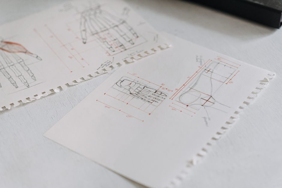
Photo by Anete Lusina on Pexels
An assembly drawing shows how multiple individual parts fit together to form a complete sub-assembly or an entire product. It focuses on the relationship and arrangement of components rather than the detailed manufacturing of each one.
Key elements of an assembly drawing include:
* Overall Views: Often isometric or orthographic views showing the assembled product.
* Part Identification (Ballooning): Numbers or letters pointing to each individual component, linking them to a parts list.
* Bill of Materials (BOM) / Parts List: A table listing all components, their part numbers, quantities, and often material.
* Assembly Instructions/Notes: Brief instructions on how parts are joined (e.g., "Fasten with M5 bolts," "Weld all around").
* Section Views: Often used to show internal relationships and how parts mate together.
The main purpose of an assembly drawing is to guide the assembly process and help in ordering components.
Relationship Between the Two
Think of the workflow: You first design and create working drawings for each unique component. Once all components are manufactured, you use the assembly drawing to put them together.
graph TD
    A["Concept & Design"] --> B["Create Individual Part Designs"]
    B --> C["Generate Working Drawing for Part A"]
    B --> D["Generate Working Drawing for Part B"]
    B --> E["Generate Working Drawing for Part C"]
    C --> F["Manufacture Part A"]
    D --> G["Manufacture Part B"]
    E --> H["Manufacture Part C"]
    F & G & H --> I["Generate Assembly Drawing"]
    I --> J["Assemble Product"]
    J --> K["Finished Product"]
3. Worked Example
Let's imagine you're designing a simple desk lamp.
Working Drawing Example (for a single part: the lamp base):
A working drawing for the lamp base would show:
* Front, top, and right-side views of the base.
* Dimensions for its overall length, width, height, and the diameter of the hole where the lamp pole inserts.
* A tolerance like "±0.5mm" for critical dimensions.
* Material specified as "Steel, Powder Coated Black."
* A note for "Drill and tap M8 hole for power cord entry."
* A title block with "Part Name: Lamp Base," "Part Number: DL-B001."
Assembly Drawing Example (for the entire lamp):
An assembly drawing for the complete desk lamp would show:
* An exploded isometric view of the lamp, showing the base, pole, shade, and bulb separated slightly.
* Balloons pointing to each component: "1" for the base, "2" for the pole, "3" for the shade, "4" for the bulb.
* A Bill of Materials table listing:
* Item 1: Lamp Base (DL-B001), Qty: 1
* Item 2: Lamp Pole (DL-P001), Qty: 1
* Item 3: Lamp Shade (DL-S001), Qty: 1
* Item 4: LED Bulb (E27-LED), Qty: 1
* ... (and so on for fasteners, wire, switch)
* Assembly notes like "Secure pole (2) into base (1) with M8 screw (item 5)," "Attach shade (3) to pole (2) with retaining ring (item 6)."
Notice how the working drawing focuses on making the base, while the assembly drawing focuses on putting the base with other parts to make the lamp.
4. Key Takeaways
- Working drawings provide all details for manufacturing a single part.
- Assembly drawings show how multiple parts fit together to form a whole.
- Working drawings include dimensions, tolerances, materials, and manufacturing notes.
- Assembly drawings feature overall views, part identification (ballooning), and a Bill of Materials.
- The working drawing guides fabrication, while the assembly drawing guides product assembly.
- Both types of drawings are crucial for effective communication in engineering.
Common Mistakes to Avoid:
- Mixing information: Don't put detailed manufacturing dimensions for individual parts on an assembly drawing.
- Incomplete information: A working drawing must be fully dimensioned and noted; ambiguity leads to errors.
- Missing BOM: An assembly drawing without a Bill of Materials is nearly useless for procurement or assembly.
- Incorrect part numbers: Ensure consistency between part numbers on balloons, the BOM, and individual working drawings.
5. Now Try It
Choose a simple everyday object, like a stapler or a coffee mug. For that object, list what information would go into:
1. A working drawing for one specific component of that object (e.g., the stapler's base, or the mug itself).
2. An assembly drawing for the entire object (even if it's just one piece like a mug, consider its handle if separate, or for the stapler, all its parts).
What success looks like: You've clearly distinguished between the type of detail each drawing requires, focusing on manufacturing specifics for the working drawing and component relationships for the assembly drawing.
Frequently asked about Working Drawings and Assembly Drawings
Study this next
Get the full Technical drawing curriculum
Clone the complete plan to your dashboard for unlimited AI-generated notes, practice quizzes, and a personalised revision schedule.
Save this course free