Introduction to Digital Systems and Computer Architecture
From the data s curriculum
TL;DR
Digital systems use discrete signals, typically binary, to represent and process information. Computer architecture describes how these components are organized and interact to execute instructions. Understanding this foundational layer helps you grasp how software runs on hardware.
1. The Mental Model
Think of a digital system as a collection of on/off switches that perform complex tasks by working together. Computer architecture is like the blueprint for how these switches (and bigger components built from them) are arranged to make a functional machine that can follow instructions.
2. The Core Material
Digital systems are built on the idea that information can be represented by a finite number of distinct states. In most modern digital systems, this means using two states: 0 and 1, often called binary. This isn't just about numbers; letters, images, sounds—everything—is ultimately converted into sequences of 0s and 1s.
Binary Representation
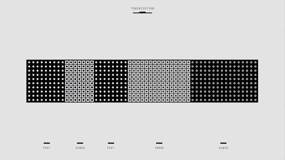
Photo by Google DeepMind on Pexels
Each 0 or 1 is called a bit. Groups of bits form larger units:
- Nibble: 4 bits
- Byte: 8 bits
- Word: A larger unit, often 16, 32, or 64 bits, depending on the computer's architecture.
Logic Gates
Photo by Syirwan Ainu on Pexels
These are the fundamental building blocks of digital circuits. They take one or more binary inputs and produce a single binary output based on a specific logical function. Common gates include:
- AND: Output is 1 only if all inputs are 1.
- OR: Output is 1 if any input is 1.
- NOT: Inverts the input (0 becomes 1, 1 becomes 0).
- XOR (Exclusive OR): Output is 1 if inputs are different.
Computer Architecture Overview
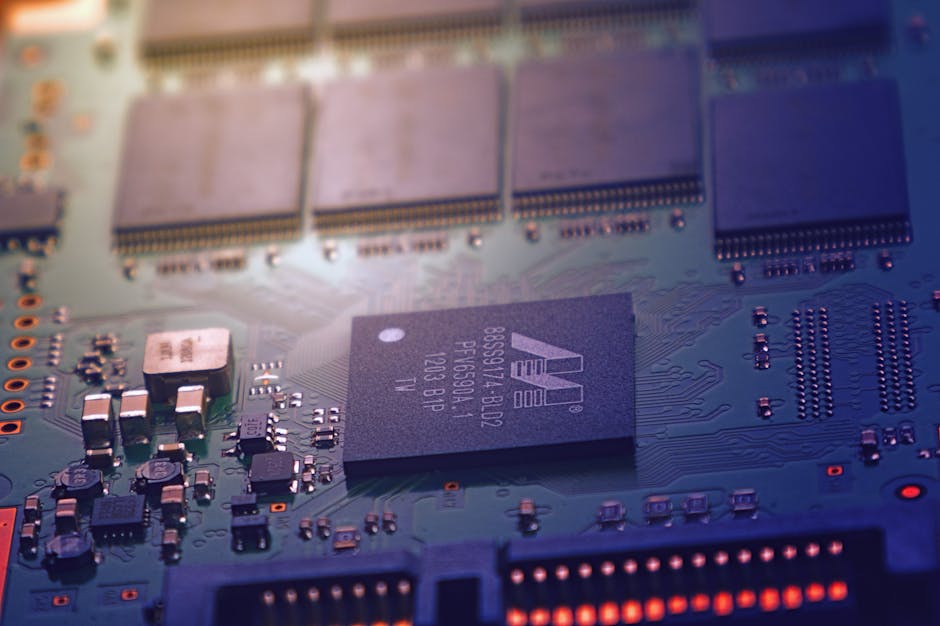
Photo by Johannes Plenio on Pexels
Computer architecture defines the functional behavior, organization, and implementation of computer systems. The most common model is the Von Neumann Architecture, which uses a single address space for both instructions and data.
Here's a simplified view of the main components:
graph TD
    A["Input Devices (Keyboard, Mouse)"] --> B["Central Processing Unit (CPU)"]
    C["Output Devices (Monitor, Printer)"] --> B
    D["Memory (RAM)"] <--> B
    E["Storage (Hard Drive, SSD)"] <--> B
    F["Bus (Data/Address/Control)"] <--> B
    F <--> D
    F <--> E
    F <--> A
    F <--> C
- CPU (Central Processing Unit): The "brain" of the computer. It executes instructions, performs calculations, and manages the flow of information. It consists of:
- ALU (Arithmetic Logic Unit): Performs arithmetic operations (add, subtract) and logical operations (AND, OR, NOT).
- Control Unit (CU): Directs and coordinates all operations within the CPU and other components. It fetches instructions, decodes them, and generates control signals.
- Registers: Small, fast storage locations within the CPU used to hold data temporarily during processing.
- Memory (RAM - Random Access Memory): Volatile storage used to hold programs and data that the CPU is currently working with. It's fast but loses its contents when the power is off.
- Storage (e.g., Hard Drive, SSD): Non-volatile storage for long-term data retention. Slower than RAM but much larger.
- Input/Output (I/O) Devices: Allow the computer to interact with the outside world (e.g., keyboard, mouse, monitor, printer).
- Bus: A set of electrical conductors that provide pathways for data, addresses, and control signals between components.
The CPU fetches an instruction from memory, decodes what it needs to do, executes it (often involving the ALU), and then stores the result back in memory or a register. This cycle repeats continuously.
3. Worked Example
Let's trace a very simple operation: adding two numbers.
Imagine you have two numbers, 5 and 3, stored in memory locations 1000 and 1001, respectively. You want to add them and store the result in memory location 1002.
- Fetch Instruction: The Control Unit (CU) fetches an instruction like "LOAD_A 1000" from memory.
- Decode Instruction: The CU decodes "LOAD_A 1000" to mean "load the value from memory address 1000 into register A."
- Execute Instruction: The CU sends a signal to memory to retrieve the value at address 1000 (which is 5). This value (5) is then moved into a CPU register, let's call it
Register_A. - Fetch Next Instruction: The CU fetches "LOAD_B 1001".
- Decode Instruction: Decodes to "load the value from memory address 1001 into register B."
- Execute Instruction: The CU retrieves the value at address 1001 (which is 3) and moves it into
Register_B. - Fetch Next Instruction: The CU fetches "ADD Register_A, Register_B".
- Decode Instruction: Decodes to "add the contents of Register_A and Register_B."
- Execute Instruction: The CU tells the ALU to add the values in
Register_A(5) andRegister_B(3). The ALU performs 5 + 3 = 8. The result (8) is stored in another register, perhapsRegister_C. - Fetch Next Instruction: The CU fetches "STORE 1002, Register_C".
- Decode Instruction: Decodes to "store the value from Register_C into memory address 1002."
- Execute Instruction: The CU sends a signal to memory to write the value from
Register_C(which is 8) into memory address 1002.
This entire sequence happens incredibly fast, millions or billions of times per second.
4. Key Takeaways
- Digital systems operate on discrete binary values (0s and 1s), representing all information this way.
- Logic gates are the elementary electronic circuits that perform basic binary operations (AND, OR, NOT).
- Computer architecture defines the structure and operation of a computer, including its main components.
- The CPU, Memory, and I/O devices are interconnected by buses to facilitate data transfer.
- The CPU's Control Unit fetches, decodes, and executes instructions, often with the help of the ALU for calculations.
- Registers are tiny, high-speed storage locations within the CPU crucial for immediate data access.
Common Mistakes to Avoid

Photo by KATRIN BOLOVTSOVA on Pexels
- Confusing volatile RAM with non-volatile long-term storage like a hard drive.
- Thinking of "digital" as only applying to numbers; it applies to all data represented by discrete states.
- Underestimating the role of the Control Unit; it's the orchestra conductor of the CPU.
- Believing that a CPU executes many instructions simultaneously in this basic model; it's typically one instruction at a time very quickly.
5. Now Try It
Imagine you're designing a very simple digital circuit for a traffic light that has two states: Red (0) and Green (1). You need to add an emergency override that, when activated, forces the light to Green, regardless of its current state.
What to do:
1. Draw a truth table for this system. Your inputs should be "Current Light State" (let's say 0 for Red, 1 for Green) and "Emergency Override" (0 for off, 1 for on). Your output is "Next Light State".
2. Based on your truth table, determine which basic logic gate (AND, OR, XOR) or combination of gates would implement this behavior.
What success looks like:
You'll have a clear truth table and an identification of a logic gate (or gates) that matches the desired output for all input combinations. For example, if both inputs are 0, the output should be 0 (Red). If override is 1, the output is always 1 (Green).
Frequently asked about Introduction to Digital Systems and Computer Architecture
Study this next
Get the full data s curriculum
Clone the complete plan to your dashboard for unlimited AI-generated notes, practice quizzes, and a personalised revision schedule.
Save this course free