Fundamentals of Electrical Circuits
From the Circuit Calculations based Kirchoff's second law curriculum
TL;DR
Electrical circuits are paths that allow electric current to flow, powered by voltage sources and limited by resistance. Understanding voltage, current, and resistance is crucial for analyzing how these circuits behave. Ohm's Law and Kirchhoff's Laws are the fundamental rules governing these relationships.
1. The Mental Model
Think of an electrical circuit like a water pipe system. The voltage is like the water pressure pushing the water, the current is the amount of water flowing, and the resistance is anything that narrows the pipe, slowing the flow.
2. The Core Material
To really get circuit calculations, you need to understand the basic building blocks: voltage, current, and resistance.
What is Voltage?
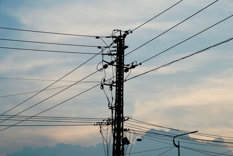
Photo by Andy Lee on Pexels
Voltage (V), measured in Volts, is the electrical potential difference between two points. It's the "push" or "force" that drives electric charge around a circuit. Imagine a battery: it creates a voltage difference that makes current flow.
What is Current?

Photo by Efrem Efre on Pexels
Current (I), measured in Amperes (Amps), is the rate of flow of electric charge. It's how many electrons pass a point in the circuit per second. If you have a higher voltage (more push) and less resistance (easier path), you'll have more current (more flow).
What is Resistance?

Photo by Luis Quintero on Pexels
Resistance (R), measured in Ohms ($\Omega$), opposes the flow of electric current. It's like friction in a pipe system. Components called resistors are specifically designed to add resistance to a circuit, controlling current flow and dropping voltage.
Ohm's Law

Photo by RDNE Stock project on Pexels
The relationship between voltage, current, and resistance is described by Ohm's Law:
$V = I \times R$
This means:
* If you know the current and resistance, you can find the voltage drop across the resistor.
* If you know the voltage and resistance, you can find the current flowing through the resistor ($I = V / R$).
* If you know the voltage and current, you can find the resistance ($R = V / I$).
Circuit Types: Series vs. Parallel
How components are connected in a circuit significantly affects how voltage and current behave.
graph TD
    A["Circuit Configuration"] --> B["Series Circuit"]
    A --> C["Parallel Circuit"]

    B --> B1["Components connected one after another"]
    B --> B2["Current is the same through all components"]
    B --> B3["Total Resistance = Sum of individual resistances"]
    B --> B4["Voltage divides across components"]

    C --> C1["Components connected across the same two points"]
    C --> C2["Voltage is the same across all components"]
    C --> C3["Total Resistance decreases as more resistors are added"]
    C --> C4["Current divides among branches"]
Series Circuits:
In a series circuit, components are connected end-to-end, forming a single path for current.
* The current is the same through every component.
* The total resistance is the sum of individual resistances ($R_{total} = R_1 + R_2 + ...$).
* The voltage supplied by the source divides across each component.
Parallel Circuits:
In a parallel circuit, components are connected across the same two points, creating multiple paths for current.
* The voltage across each parallel component is the same.
* The total current is the sum of the currents in each branch.
* The reciprocal of the total resistance is the sum of the reciprocals of individual resistances ($1/R_{total} = 1/R_1 + 1/R_2 + ...$). This means adding more resistors in parallel decreases the total resistance.
3. Worked Example
Let's say you have a simple series circuit with a 9V battery and two resistors: $R_1 = 100 \Omega$ and $R_2 = 200 \Omega$.
-
Find the total resistance ($R_{total}$):
Since they're in series, $R_{total} = R_1 + R_2 = 100 \Omega + 200 \Omega = 300 \Omega$. -
Find the total current ($I_{total}$):
Using Ohm's Law, $I_{total} = V / R_{total} = 9V / 300 \Omega = 0.03 A$ (or 30mA).
Remember, in a series circuit, this current is the same through both resistors. -
Find the voltage drop across each resistor ($V_1$ and $V_2$):
For $R_1$: $V_1 = I_{total} \times R_1 = 0.03 A \times 100 \Omega = 3V$.
For $R_2$: $V_2 = I_{total} \times R_2 = 0.03 A \times 200 \Omega = 6V$.
Notice that $V_1 + V_2 = 3V + 6V = 9V$, which equals the battery voltage (Kirchhoff's Voltage Law in action!).
4. Key Takeaways
- Voltage is the electrical "push" or potential difference that drives current.
- Current is the flow rate of electric charge.
- Resistance opposes current flow and converts electrical energy into heat.
- Ohm's Law ($V=IR$) is the fundamental relationship between these three quantities.
- In series circuits, current is constant, and resistances add up.
- In parallel circuits, voltage is constant across branches, and current divides.
- Total resistance in parallel circuits is always less than the smallest individual resistance.
Common Mistakes to Avoid:
- Confusing series and parallel rules for current and voltage.
- Forgetting that total resistance in parallel circuits decreases as you add more paths.
- Incorrectly applying Ohm's Law (e.g., using total voltage with individual resistance in a series circuit to find individual current).
- Not paying attention to units (Volts, Amps, Ohms).
5. Now Try It
You have a 12V battery connected to two parallel resistors: $R_1 = 60 \Omega$ and $R_2 = 30 \Omega$. Calculate the total resistance of the circuit, the total current drawn from the battery, and the current flowing through each individual resistor.
What success looks like: You should be able to clearly show the steps to find $R_{total}$, $I_{total}$, $I_1$, and $I_2$, with correct numerical answers.
Frequently asked about Fundamentals of Electrical Circuits
Study this next
Get the full Circuit Calculations based Kirchoff's second law curriculum
Clone the complete plan to your dashboard for unlimited AI-generated notes, practice quizzes, and a personalised revision schedule.
Save this course free