Interference in Thin Films
From the engineering physics curriculum
TL;DR
When light interacts with a thin film, reflections from its top and bottom surfaces can interfere, either constructively or destructively. This interference depends on the film's thickness, its refractive index, and the wavelength of the light. We see this phenomenon as colorful patterns in soap bubbles or oil slicks.
1. The Mental Model
Imagine light waves hitting a thin, transparent layer like a soap bubble. Some light reflects off the very top surface, while some goes through, reflects off the bottom surface, and then emerges. These two reflected light waves then combine, creating an interference pattern.
2. The Core Material
Interference in thin films occurs because light waves reflect off different surfaces of the film and then recombine. The key is the path difference between these two reflected waves and any phase changes upon reflection.
Here's how it breaks down:
Reflections and Phase Changes
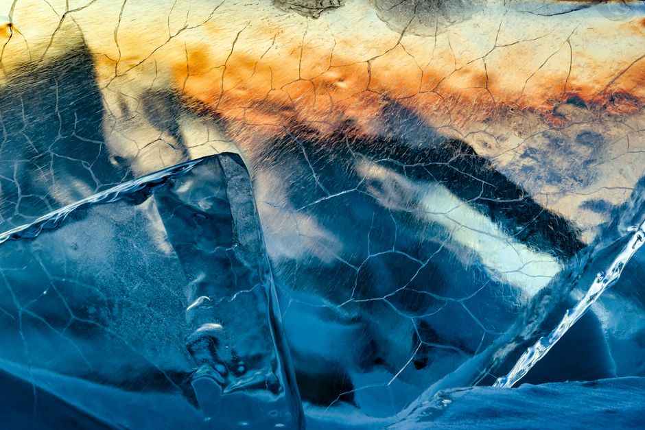
Photo by Sergey Pesterev on Pexels
When light reflects, its phase might change by 180 degrees (or $\pi$ radians). This happens if the light goes from a medium with a lower refractive index ($n_1$) to a medium with a higher refractive index ($n_2$). If $n_1 < n_2$, a phase change occurs. If $n_1 > n_2$, no phase change occurs.
Consider a thin film (refractive index $n_f$) sandwiched between two other media (e.g., air $n_a$ and glass $n_g$).
- Reflection 1 (Top Surface): Light reflects off the interface between the incident medium (e.g., air) and the film.
- Reflection 2 (Bottom Surface): Light enters the film, travels through it, reflects off the interface between the film and the substrate (e.g., glass), and then travels back out through the film to recombine with Reflection 1.
Path Difference

Photo by wal_ 172619 on Pexels
The light reflecting from the bottom surface travels an extra distance inside the film. For light hitting the film approximately perpendicularly, this extra distance is roughly twice the film's thickness ($2t$).
However, because light travels slower in a medium with a higher refractive index, we must use the optical path difference (OPD), which is $2n_f t$.
Conditions for Constructive and Destructive Interference
Photo by Serhii Bondarchuk on Pexels
We need to combine the optical path difference with any phase changes due to reflection.
Here's a flowchart to help visualize the conditions:
graph TD
    A["Light Wave Incident on Film"] --> B{"Phase Change at First Surface?"}
    B -- "Yes (e.g., air -> film)" --> C["Phase Shift 180° (π)"]
    B -- "No (e.g., film -> air)" --> D["No Phase Shift"]

    A --> E{"Phase Change at Second Surface?"}
    E -- "Yes (e.g., film -> glass)" --> F["Phase Shift 180° (π)"]
    E -- "No (e.g., film -> air)" --> G["No Phase Shift"]

    C --> H["Total Phase Shifts: 180°"]
    D --> I["Total Phase Shifts: 0°"]
    F --> J["Total Phase Shifts: 180°"]
    G --> K["Total Phase Shifts: 0°"]

    H -- "Combined with K" --> L["Effective Relative Phase Shift: 180°"]
    I -- "Combined with J" --> L
    C -- "Combined with J" --> M["Effective Relative Phase Shift: 0°"]
    D -- "Combined with K" --> M

    M --> P{"Optical Path Difference (OPD) = 2n_f t"}
    L --> Q{"Optical Path Difference (OPD) = 2n_f t"}

    P -- "OPD = mλ_air (m=0,1,2...)" --> R["Constructive Interference"]
    P -- "OPD = (m+1/2)λ_air" --> S["Destructive Interference"]

    Q -- "OPD = mλ_air (m=0,1,2...)" --> S
    Q -- "OPD = (m+1/2)λ_air" --> R
(Note: $\lambda_{air}$ is the wavelength of light in air/vacuum.)
In most common scenarios (like a soap film in air or an oil slick on water), the first reflection (air to film) has a 180° phase shift, and the second reflection (film to air/water) might not, or vice versa, leading to one overall effective phase shift of 180°.
If there's one effective 180° phase change:
* Constructive Interference (bright fringe): $2n_f t = (m + 1/2) \lambda_{air}$ (where m = 0, 1, 2, ...)
* Destructive Interference (dark fringe): $2n_f t = m \lambda_{air}$ (where m = 0, 1, 2, ...)
If there are zero or two effective 180° phase changes (i.e., no net relative phase shift from reflections):
* Constructive Interference (bright fringe): $2n_f t = m \lambda_{air}$ (where m = 0, 1, 2, ...)
* Destructive Interference (dark fringe): $2n_f t = (m + 1/2) \lambda_{air}$ (where m = 0, 1, 2, ...)
Remember, $\lambda_{air}$ is the wavelength of light in vacuum or air, and $n_f$ is the refractive index of the film.
3. Worked Example
Let's say you have an oil slick ($n_{oil} = 1.45$) on water ($n_{water} = 1.33$). Light shines down on it from air ($n_{air} = 1.00$). What thickness of oil film would appear bright (constructive interference) for green light ($\lambda_{air} = 550 \text{ nm}$)?
First, let's analyze the phase shifts:
1. Air to Oil: $n_{air} (1.00) < n_{oil} (1.45)$. So, a 180° phase change occurs for the first reflected ray.
2. Oil to Water: $n_{oil} (1.45) > n_{water} (1.33)$. So, no phase change occurs for the second reflected ray.
Since there's only one effective 180° phase change, we use the condition for constructive interference:
$2n_f t = (m + 1/2) \lambda_{air}$
We want the thinnest film, so we choose $m = 0$.
$2n_{oil} t = (0 + 1/2) \lambda_{air}$
$2n_{oil} t = \frac{1}{2} \lambda_{air}$
Now, plug in the values:
$2 \times 1.45 \times t = \frac{1}{2} \times 550 \text{ nm}$
$2.90 \times t = 275 \text{ nm}$
$t = \frac{275 \text{ nm}}{2.90}$
$t \approx 94.8 \text{ nm}$
So, an oil film about 94.8 nm thick would appear bright green.
4. Key Takeaways
- Interference in thin films results from two reflected light waves combining.
- The two main factors determining interference are the optical path difference and any phase changes upon reflection.
- A phase change of 180° occurs when light reflects off an interface with a higher refractive index medium.
- The conditions for constructive/destructive interference swap depending on the total number of 180° phase shifts between the two reflected rays.
- The optical path difference is $2n_f t$ for normal incidence, where $n_f$ is the film's refractive index and $t$ is its thickness.
- Different colors (wavelengths) will interfere differently, explaining the vibrant patterns in soap bubbles and oil slicks.
Common Mistakes to Avoid

Photo by KATRIN BOLOVTSOVA on Pexels
- Forgetting to consider phase changes upon reflection. This is often the trickiest part!
- Using the wavelength in the film ($\lambda_f = \lambda_{air}/n_f$) instead of the air wavelength ($\lambda_{air}$) when using the $2n_f t$ formula. Stick to $\lambda_{air}$ in the equations provided.
- Confusing the conditions for constructive/destructive interference, especially when phase shifts are involved.
- Assuming "thinnest" always means $m=0$; it does for constructive interference but for destructive interference, $m$ can be 0 or higher.
- Not paying attention to whether the incident light is normal or at an angle (these notes assume normal incidence).
5. Now Try It
You have a thin coating ($n_c = 1.30$) on a glass lens ($n_g = 1.50$) to reduce reflection of blue light ($\lambda_{air} = 450 \text{ nm}$). What's the minimum non-zero thickness of the coating required for destructive interference of blue light?
Success looks like: Finding a single thickness value in nanometers for the coating. Make sure to clearly state your phase change analysis and which interference condition you used.
Frequently asked about Interference in Thin Films
Study this next
Get the full engineering physics curriculum
Clone the complete plan to your dashboard for unlimited AI-generated notes, practice quizzes, and a personalised revision schedule.
Save this course free