CPU Structure and Function
From the Computer Organisation and Architecture curriculum
TL;DR
The CPU (Central Processing Unit) is the "brain" of a computer, responsible for executing program instructions and performing calculations. It's made of key components like the Control Unit, ALU, and Registers, which work together in a fetch-decode-execute cycle. Understanding these parts helps you grasp how software commands turn into hardware actions.
1. The Mental Model
Think of the CPU as a highly organized, super-fast factory. It receives instructions (like blueprints), figures out what to do with them, performs the necessary work (calculations, data movement), and then stores the results, all in a relentless, precise loop.
2. The Core Material
The CPU isn't a single, monolithic block; it's a collection of specialized units that cooperate closely. Understanding these units is key to understanding how a computer processes information.
2.1 Key Components of the CPU
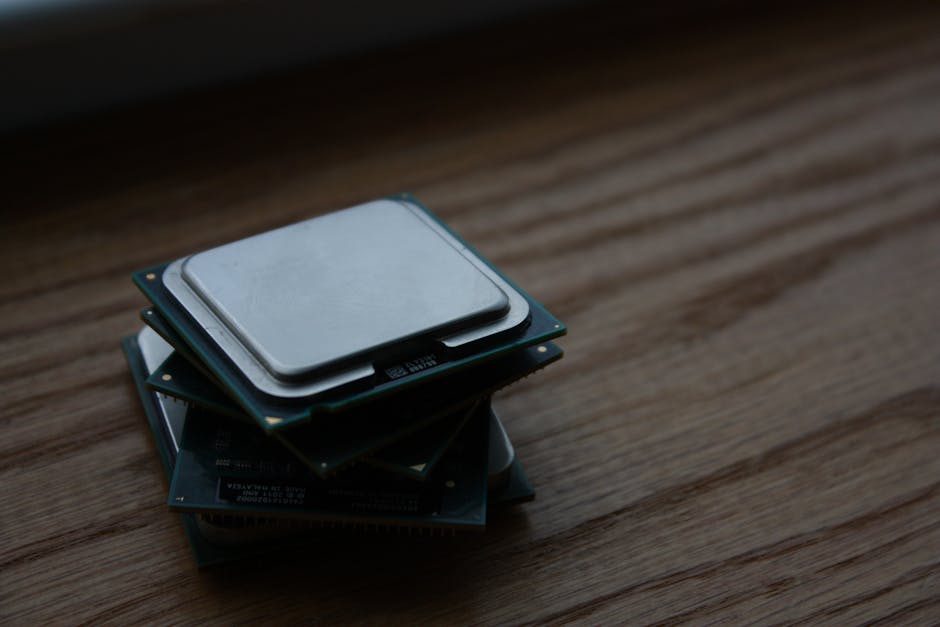
Photo by Shawn Stutzman on Pexels
-
Arithmetic Logic Unit (ALU): This is the CPU's calculator and logic solver. It performs arithmetic operations (like addition, subtraction, multiplication, division) and logical operations (like AND, OR, NOT, comparisons). If an instruction requires a mathematical calculation or a logical decision, the ALU handles it.
-
Control Unit (CU): The CU is the orchestra conductor of the CPU. It manages and coordinates all the CPU's components. It fetches instructions from memory, decodes them (figures out what they mean), and then directs other components (like the ALU or registers) to perform the necessary actions. It ensures instructions are executed in the correct sequence.
-
Registers: These are small, super-fast storage locations directly inside the CPU. They hold data and instructions that the CPU is currently working on. Think of them as tiny scratchpads or temporary holding areas. There are several types:
- Program Counter (PC): Holds the memory address of the next instruction to be fetched.
- Instruction Register (IR): Holds the current instruction being executed.
- Memory Address Register (MAR): Holds the memory address of the data or instruction that needs to be accessed (read from or written to).
- Memory Data Register (MDR): Holds the data being transferred to or from memory.
- General-Purpose Registers: Used for temporary storage of data during calculations or data manipulation.
2.2 The Fetch-Decode-Execute Cycle
This is the fundamental operation of the CPU, constantly repeating as long as the computer is running. It's often called the instruction cycle.
-
Fetch: The CU fetches the next instruction from main memory.
- The address of the next instruction is copied from the Program Counter (PC) to the Memory Address Register (MAR).
- The instruction at that address is then fetched from memory and placed into the Memory Data Register (MDR).
- Finally, the instruction is moved from the MDR to the Instruction Register (IR).
- The PC is then incremented to point to the next instruction.
-
Decode: The CU decodes the instruction currently in the Instruction Register. It interprets what the instruction means (e.g., "add these two numbers," "load data from memory," "store data"). This involves breaking down the instruction into its opcode (the operation to perform) and operands (the data or addresses to operate on).
-
Execute: The CU directs the appropriate components to carry out the instruction.
- If it's an arithmetic or logic operation, the CU tells the ALU to perform it, using data from registers.
- If it's a data transfer, the CU manages moving data between registers, memory, or I/O devices.
- Results are often stored back into registers or memory.
-
Store (Write-back): (Sometimes considered part of "Execute" or a separate phase.) The results of the execution are written back to a register or to main memory, as specified by the instruction.
Here’s a simplified visual of the cycle:
graph TD
    A["Start: Program Counter (PC) has next instruction address"] --> B["Fetch: Copy PC to MAR"]
    B --> C["Fetch: Get instruction from Memory at MAR address"]
    C --> D["Fetch: Put instruction into MDR, then IR"]
    D --> E["Fetch: Increment PC"]
    E --> F["Decode: CU interprets instruction in IR"]
    F --> G{"Execute: What kind of instruction?"}
    G -- "Arithmetic/Logic" --> H["ALU performs operation (e.g., add, compare)"]
    G -- "Data Transfer" --> I["Move data between registers/memory"]
    G -- "Control Flow" --> J["Change PC for branch/jump"]
    H --> K["Store Result (e.g., in register/memory)"]
    I --> K
    J --> A
    K --> A
2.3 Buses
Buses are pathways that transmit data between different components within the computer. They're essential for the CPU to communicate with memory, I/O devices, and even its own internal units.
* Data Bus: Carries the actual data being transferred.
* Address Bus: Carries the memory address or I/O port address for data access.
* Control Bus: Carries control signals (e.g., read/write signals, clock signals) that coordinate operations.
3. Worked Example
Let's trace a very simple instruction: ADD R1, R2 (meaning "add the value in Register R2 to the value in Register R1, and store the result in R1"). Assume R1 currently holds 5 and R2 holds 3.
- Initial State: The Program Counter (PC) holds the memory address of the
ADD R1, R2instruction. - Fetch:
- The Control Unit (CU) copies the PC's content (the instruction's address) to the Memory Address Register (MAR).
- The instruction
ADD R1, R2is retrieved from memory at the MAR's address and put into the Memory Data Register (MDR). - The CU moves the instruction from MDR to the Instruction Register (IR).
- The PC is incremented to point to the next instruction in sequence.
- Decode:
- The CU analyzes the
ADD R1, R2instruction in the IR. It understands this means an addition operation, involving registers R1 and R2, with the result going back into R1.
- The CU analyzes the
- Execute:
- The CU tells the ALU to perform an addition.
- The values from R1 (5) and R2 (3) are sent to the ALU.
- The ALU calculates 5 + 3 = 8.
- Store (Write-back):
- The ALU's result (8) is sent back to Register R1, overwriting its previous value. R1 now holds 8.
- Cycle Repeats: The CPU then fetches the next instruction pointed to by the (now incremented) PC.
4. Key Takeaways
- The CPU is composed of specialized units: the ALU (calculations), CU (orchestration), and Registers (fast temporary storage).
- The Program Counter (PC) is crucial, always pointing to the next instruction to keep the program flowing.
- The instruction cycle (Fetch-Decode-Execute) is the fundamental process by which the CPU runs programs.
- Registers provide extremely fast access to data and instructions that the CPU is actively using.
- Buses are the communication highways, carrying addresses, data, and control signals between components.
Common Mistakes to Avoid:
- Confusing the roles of the ALU and CU; the ALU calculates, the CU directs.
- Thinking all data goes to/from main memory for every operation; registers are used for immediate, active data.
- Underestimating the importance of the Program Counter; without it, the CPU wouldn't know what to do next.
- Forgetting that the CPU is constantly performing the fetch-decode-execute cycle, even for simple tasks.
5. Now Try It
Imagine a simple instruction: LOAD R3, [1000], which means "load the value from memory address 1000 into Register R3."
Describe, step-by-step, how the CPU would execute this instruction, detailing what each main component (PC, MAR, MDR, IR, CU, R3, main memory) does during each phase (Fetch, Decode, Execute, Store). What would be in R3 after execution if memory location 1000 contains the value 42?
Success looks like a clear, sequential description of how the instruction moves through the CPU's components, identifying the role of each part at every step.
Frequently asked about CPU Structure and Function
More from Computer Organisation and Architecture
Get the full Computer Organisation and Architecture curriculum
Clone the complete plan to your dashboard for unlimited AI-generated notes, practice quizzes, and a personalised revision schedule.
Save this course free