"Concept of internal resistance of a source",
From the Current electricity II curriculum
TL;DR
Every real-world power source, like a battery, has some internal resistance that limits the actual voltage it can deliver to a circuit. This internal resistance causes some of the source's energy to be lost as heat within the source itself when current flows. You can think of it as a small resistor connected in series with an ideal voltage source inside the battery.
1. The Mental Model
Imagine a battery isn't just a perfect voltage source, but actually a perfect source with a tiny, hidden resistor built right inside it. This hidden resistor is the internal resistance, and it's always there, even if you can't see it.
2. The Core Material
When you think of a battery, you usually think of its electromotive force (EMF), often called the ideal voltage. This is the maximum potential difference the battery can provide when no current is flowing (like when it's sitting on a shelf). However, when you connect the battery to a circuit and draw current, the voltage you actually measure across its terminals (the terminal voltage) will be a bit lower than the EMF. Why? Because of internal resistance.
What is Internal Resistance?
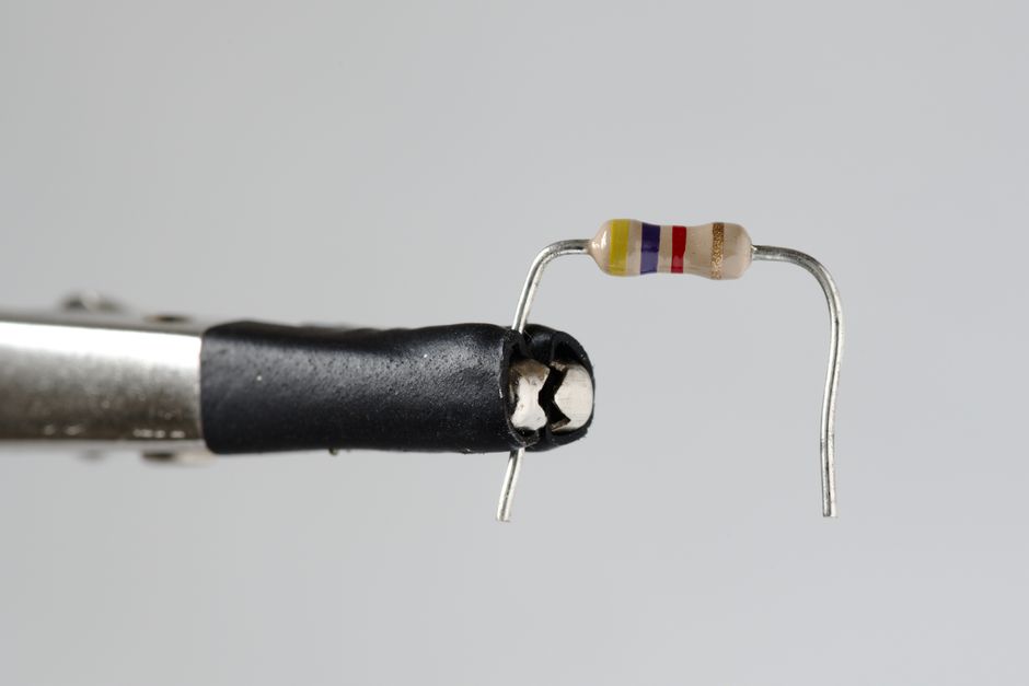
Photo by Zacharias Korsalka on Pexels
Internal resistance ($r$) is simply the opposition to current flow within the source itself. It's caused by the materials the battery is made of – the electrolytes, electrodes, and any connecting wires inside. It converts some of the electrical energy into heat within the battery, so not all the EMF is available at the terminals.
The Relationship: EMF, Terminal Voltage, and Internal Resistance

Photo by cottonbro studio on Pexels
Here's the key relationship:
The EMF ($E$) of the source is the total potential difference it can generate.
When current ($I$) flows through the internal resistance ($r$), a voltage drop occurs across it, given by Ohm's law: $V_r = I \times r$.
The terminal voltage ($V_t$) is what's left over and delivered to your external circuit.
So, the equation linking them is:
$V_t = E - I \times r$
This equation tells you that the terminal voltage is always less than or equal to the EMF. It's only equal to the EMF when no current is flowing ($I=0$), or if the internal resistance were zero (which it never is in a real source).
Let's look at how this impacts a circuit:
graph TD
    A["Ideal Voltage Source (EMF, E)"] --> B["Internal Resistor (r)"]
    B --> C["Terminal 1 (+)"]
    C -- Current (I) --> D["External Load Resistor (R_L)"]
    D --> E["Terminal 2 (-)"]
    E --> A
    subgraph Battery
        A
        B
        C
        E
    end
    subgraph External Circuit
        D
    end
In the diagram, the battery is represented by an ideal voltage source (EMF) in series with its internal resistance ($r$). When you connect an external load resistor ($R_L$), current ($I$) flows through the entire circuit.
The total resistance in the circuit is the sum of the external load resistance and the internal resistance: $R_{total} = R_L + r$.
Using Ohm's Law for the entire circuit:
$I = \frac{E}{R_{total}} = \frac{E}{R_L + r}$
Now, substitute this $I$ back into the terminal voltage equation:
$V_t = E - \left( \frac{E}{R_L + r} \right) \times r$
Alternatively, the terminal voltage is also the voltage across the external load resistor ($R_L$):
$V_t = I \times R_L$
Both equations for $V_t$ should give you the same result. The first one highlights the "loss" due to internal resistance, while the second shows what's actually available to the external circuit.
Factors Affecting Internal Resistance
- Age of the battery: Older batteries tend to have higher internal resistance.
- Temperature: Internal resistance can vary with temperature.
- Battery chemistry: Different types of batteries (e.g., alkaline, lithium-ion) have different internal resistance characteristics.
- State of charge: A nearly discharged battery often has higher internal resistance.
3. Worked Example
Let's say you have a battery with an EMF of 12 V. When you connect it to an external resistor of 5 Ω, a current of 2 A flows through the circuit. We want to find the internal resistance of the battery and the terminal voltage.
-
Calculate the terminal voltage ($V_t$):
The terminal voltage is the voltage across the external load resistor.
$V_t = I \times R_L$
$V_t = 2 \text{ A} \times 5 \text{ Ω}$
$V_t = 10 \text{ V}$ -
Calculate the internal resistance ($r$):
We use the formula: $V_t = E - I \times r$
We know $V_t = 10 \text{ V}$, $E = 12 \text{ V}$, and $I = 2 \text{ A}$.
$10 \text{ V} = 12 \text{ V} - (2 \text{ A} \times r)$
Rearrange to solve for $r$:
$2 \text{ A} \times r = 12 \text{ V} - 10 \text{ V}$
$2 \text{ A} \times r = 2 \text{ V}$
$r = \frac{2 \text{ V}}{2 \text{ A}}$
$r = 1 \text{ Ω}$
So, the internal resistance of the battery is 1 Ω, and the terminal voltage delivered to the 5 Ω resistor is 10 V. Notice that the terminal voltage (10 V) is less than the EMF (12 V) because of the voltage drop across the internal resistance ($I \times r = 2 \text{ A} \times 1 \text{ Ω} = 2 \text{ V}$).
4. Key Takeaways
- EMF ($E$) is the ideal, maximum voltage a source provides without current flow.
- Internal resistance ($r$) is inherent to all real power sources, limiting output.
- Terminal voltage ($V_t$) is the actual voltage available at the source's terminals when current flows.
- Voltage drop ($I \times r$) occurs across the internal resistance, reducing terminal voltage from EMF.
- The relationship is $V_t = E - I \times r$.
- Internal resistance causes energy loss as heat within the source itself.
- A higher internal resistance means a larger voltage drop and less power delivered to the external circuit for a given current.
Common Mistakes to Avoid

Photo by Roman Koval on Pexels
- Confusing EMF with terminal voltage: They are only equal when no current is drawn or if the internal resistance were zero.
- Ignoring internal resistance: Always consider it for real-world circuit analysis, especially with high currents or sensitive loads.
- Assuming internal resistance is constant: It can change with factors like battery age, temperature, and state of charge.
- Applying Ohm's law ($V=IR$) to EMF directly with external resistance only: Remember, total resistance is $R_{load} + r$.
5. Now Try It
You have a car battery with an EMF of 12.6 V. When you turn on the headlights, a total current of 6 A flows from the battery, and the voltage measured across the battery terminals drops to 12.0 V. Your task is to calculate the internal resistance of the car battery. Show your steps clearly. Success means correctly finding the internal resistance in ohms.
Try it yourself: Series and parallel circuits in 3D
Frequently asked about "Concept of internal resistance of a source",
More from Current electricity II
Get the full Current electricity II curriculum
Clone the complete plan to your dashboard for unlimited AI-generated notes, practice quizzes, and a personalised revision schedule.
Save this course free