Series Circuits: Characteristics and Behavior
From the Science curriculum
Series Circuits: Characteristics and Behavior
TL;DR
In a series circuit, all components are connected end-to-end, forming a single path for electricity. This means the current is the same everywhere, but the voltage drops across each component add up to the total supply voltage. Total resistance is simply the sum of individual resistances.
1. The Mental Model
Imagine a single-lane road with a few speed bumps. Every car on that road has to go over every speed bump, one after another. That's a series circuit: current is the cars, components are the speed bumps, and there's only one path.
2. The Core Material
When you connect components in a series circuit, you're creating one continuous loop. Think of old Christmas lights where if one bulb went out, the whole string died – that's a classic series circuit characteristic.
Here's how they behave:
Current (I)

Photo by William Hadley on Pexels
Since there's only one path for the electrons to flow, the current is the same everywhere in a series circuit. If you measure the current at any point, you'll get the same value.
$$I_{total} = I_1 = I_2 = I_3 = \dots$$
Voltage (V)
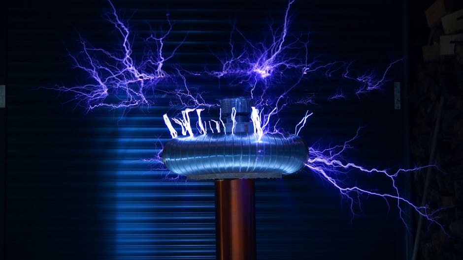
Photo by Killian Eon on Pexels
The total voltage supplied by the battery or power source gets divided up among the components. Each component "uses up" a part of the total voltage. The sum of the voltage drops across each component equals the total supply voltage.
$$V_{total} = V_1 + V_2 + V_3 + \dots$$
Resistance (R)
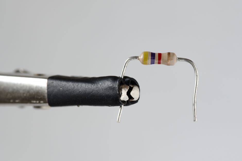
Photo by Zacharias Korsalka on Pexels
Adding more resistors in series directly increases the total resistance of the circuit. It's like adding more speed bumps to our single-lane road; the overall opposition to the flow increases.
$$R_{total} = R_1 + R_2 + R_3 + \dots$$
This also means that if you increase the total resistance, and the voltage stays the same, the total current will decrease (thanks, Ohm's Law: $V=IR$).
graph LR
    A["Power Source (+ terminal)"] --> B["Resistor 1 (R1)"]
    B --> C["Resistor 2 (R2)"]
    C --> D["Resistor 3 (R3)"]
    D --> E["Power Source (- terminal)"]

    subgraph "Voltage Drops"
        B -- "V1" --> C
        C -- "V2" --> D
    end

    subgraph "Current Path"
        A -- "I" --> B
        B -- "I" --> C
        C -- "I" --> D
        D -- "I" --> E
    end

    style A fill:#f9f,stroke:#333,stroke-width:2px
    style E fill:#f9f,stroke:#333,stroke-width:2px
What Happens if a Component Fails?

Photo by Ann H on Pexels
If one component in a series circuit breaks or creates an open circuit (like a blown fuse or a disconnected wire), the entire circuit breaks. No current can flow anywhere, and all other components will stop working. This is why those old Christmas lights were so frustrating!
3. Worked Example
Let's say you have a 12V battery connected to three resistors in series: $R_1 = 2 \Omega$, $R_2 = 4 \Omega$, and $R_3 = 6 \Omega$.
-
Calculate the total resistance ($R_{total}$):
$R_{total} = R_1 + R_2 + R_3 = 2 \Omega + 4 \Omega + 6 \Omega = 12 \Omega$. -
Calculate the total current ($I_{total}$):
Using Ohm's Law ($V = IR$, so $I = V/R$):
$I_{total} = V_{total} / R_{total} = 12V / 12 \Omega = 1A$. -
Calculate the voltage drop across each resistor:
Since the current is the same everywhere in a series circuit ($I_1 = I_2 = I_3 = 1A$):
$V_1 = I_1 \times R_1 = 1A \times 2 \Omega = 2V$
$V_2 = I_2 \times R_2 = 1A \times 4 \Omega = 4V$
$V_3 = I_3 \times R_3 = 1A \times 6 \Omega = 6V$ -
Verify that the sum of voltage drops equals the total voltage:
$V_1 + V_2 + V_3 = 2V + 4V + 6V = 12V$. This matches the battery voltage, so our calculations are correct!
4. Key Takeaways
- The current is identical at every point in a series circuit.
- The total voltage supplied is divided among the components.
- The sum of voltage drops across all components equals the total supply voltage.
- To find total resistance, you simply add up the individual resistances.
- Breaking one component stops current flow for the entire circuit.
- Adding more resistance in series decreases the total current (for a constant voltage).
- Components in series share the same single current path.
Common mistakes to avoid:
- Don't assume voltage is the same across all components in series; it divides.
- Don't forget that if one component fails, the whole circuit fails.
- Never add up currents in a series circuit; current is constant throughout.
- Don't apply Ohm's Law for a single resistor using the total circuit voltage; use the voltage across that specific resistor.
5. Now Try It
You have a 9V battery and want to light up two identical small light bulbs (each with a resistance of $3 \Omega$) in series.
- Draw a simple schematic diagram of this circuit.
- Calculate the total resistance of the circuit.
- Calculate the total current flowing through the circuit.
- Calculate the voltage drop across each individual light bulb.
What you should find is that the total resistance is $6 \Omega$, the total current is $1.5A$, and each bulb has a $4.5V$ drop across it.
Frequently asked about Series Circuits: Characteristics and Behavior
More from Science
Get the full Science curriculum
Clone the complete plan to your dashboard for unlimited AI-generated notes, practice quizzes, and a personalised revision schedule.
Create Free Account