Fundamentals of Electric Circuits
From the Science curriculum
Fundamentals of Electric Circuits
TL;DR
Electric circuits move energy using flowing charges, driven by a "push" and limited by "resistance." Understanding voltage, current, and resistance helps you predict how circuits behave and build useful devices. Ohm's Law is the key relationship for many basic circuits.
1. The Mental Model
Think of electricity like water flowing in pipes. Voltage is the water pressure pushing the water, current is how much water flows per second, and resistance is anything that narrows the pipe or slows the flow.
2. The Core Material
Electric circuits are all about moving electrical energy from one place to another to do work, like lighting a bulb or powering your phone. To understand them, you need to grasp three fundamental concepts: voltage, current, and resistance.
Voltage (V)
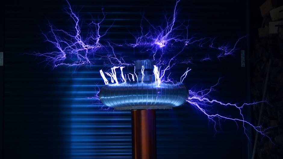
Photo by Killian Eon on Pexels
Voltage, measured in volts (V), is the "push" or potential energy difference that causes electric charges to move. Imagine a battery: it creates a voltage difference between its positive and negative terminals. Without voltage, there's no force to make charges flow.
Current (I)

Photo by William Hadley on Pexels
Current, measured in amperes (A), is the rate of flow of electric charge. It tells you how many electrons are passing a point in the circuit per second. Think of it as the volume of water flowing through a pipe. A higher current means more charges are moving.
Resistance (R)
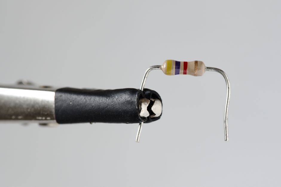
Photo by Zacharias Korsalka on Pexels
Resistance, measured in ohms (Ω), is the opposition to the flow of electric current. Materials that resist current flow a lot are called insulators (like rubber), while materials that resist very little are conductors (like copper wire). Resistors are components specifically designed to add a certain amount of resistance to a circuit.
Ohm's Law
Photo by Zacharias Korsalka on Pexels
These three concepts are tied together by Ohm's Law, which is one of the most important relationships in basic electronics. It states:
Voltage (V) = Current (I) × Resistance (R)
You can rearrange this to find any of the three if you know the other two:
* I = V / R (Current equals Voltage divided by Resistance)
* R = V / I (Resistance equals Voltage divided by Current)
This law helps you predict how a circuit will behave. If you increase the voltage across a resistor, the current through it will increase. If you increase the resistance, the current will decrease (for the same voltage).
Series and Parallel Circuits
Components in a circuit can be connected in two basic ways: series or parallel.
graph TD
    A["Circuit"] --> B["Component Arrangement"]
    B --> C["Series Connection"]
    B --> D["Parallel Connection"]

    C --> C1["(One path for current)"]
    C --> C2["(Total resistance adds up)"]
    C --> C3["(Current is same everywhere)"]

    D --> D1["(Multiple paths for current)"]
    D --> D2["(Total resistance is less than smallest)"]
    D --> D3["(Voltage is same across branches)"]
-
Series Connection: Components are connected end-to-end, forming a single path for the current.
- The total resistance is the sum of individual resistances:
R_total = R1 + R2 + ... - The current is the same through every component.
- The voltage divides across the components.
- The total resistance is the sum of individual resistances:
-
Parallel Connection: Components are connected across the same two points, providing multiple paths for the current.
- The total resistance is less than the smallest individual resistance (current has more paths to take). The formula for two resistors is
R_total = (R1 * R2) / (R1 + R2). - The voltage is the same across all parallel components.
- The current divides among the branches.
- The total resistance is less than the smallest individual resistance (current has more paths to take). The formula for two resistors is
3. Worked Example
Let's say you have a 9V battery and you want to light up an LED. LEDs usually need about 20mA (0.02A) of current to glow brightly without burning out. An LED also has a "forward voltage" — a certain voltage it "drops" or uses up. Let's assume your LED drops 2V.
To calculate the resistor you need to add in series with the LED to limit the current, you first figure out the voltage remaining for the resistor.
-
Calculate voltage across the resistor:
Battery voltage - LED voltage drop = Voltage for resistor
9V - 2V = 7V -
Use Ohm's Law to find the required resistance:
R = V / I
R = 7V / 0.02A
R = 350 Ω
So, you'd need a 350 Ohm resistor (or the closest standard value, like 330 Ohm or 360 Ohm) in series with your LED and 9V battery to get roughly 20mA of current through the LED.
4. Key Takeaways
- Voltage (V) is the electrical "push" that drives current.
- Current (I) is the flow rate of electric charge.
- Resistance (R) opposes current flow.
- Ohm's Law (V = I × R) describes the relationship between these three.
- In a series circuit, current is constant, and resistance adds up.
- In a parallel circuit, voltage is constant, and current splits.
- Always use a current-limiting resistor with LEDs to prevent damage.
Common Mistakes to Avoid:
- Forgetting units (volts, amps, ohms) in calculations.
- Confusing voltage with current; they're related but distinct.
- Not accounting for component voltage drops (like LEDs) when calculating required resistors.
- Connecting components directly to power without appropriate resistance, potentially leading to short circuits or damage.
5. Now Try It
Take a 12V power supply and a 100 Ohm resistor. Calculate the current that will flow through the resistor if you connect it directly across the 12V supply. What would happen to the current if you then added another 100 Ohm resistor in series with the first one? What if you added it in parallel?
Success means you can calculate the current for each scenario using Ohm's Law and the rules for series and parallel resistance.
Frequently asked about Fundamentals of Electric Circuits
More from Science
Get the full Science curriculum
Clone the complete plan to your dashboard for unlimited AI-generated notes, practice quizzes, and a personalised revision schedule.
Create Free Account