OSI Model and Network Devices
From the network + curriculum
TL;DR
The OSI Model breaks down network communication into seven layers, helping you understand how data travels. Each layer handles specific tasks, from physical connections to application interaction. Network devices operate at different OSI layers, performing functions essential for data transfer and network management.
1. The Mental Model
Think of the OSI Model as a recipe with seven steps for sending a letter. Each step prepares the letter differently, adds necessary information, and then passes it to the next step until it's ready to be mailed. On the receiving end, the process reverses, unpacking the letter step-by-step.
2. The Core Material
The Open Systems Interconnection (OSI) Model is a conceptual framework that standardizes how communication systems function. It divides network communication into seven distinct layers, each responsible for a specific part of the process.
Here are the layers, from top (closest to the user) to bottom (closest to the physical cable):
The Seven Layers of the OSI Model
- Application Layer (Layer 7): This is where you, the user, interact with the network. It provides network services to applications. Think of web browsers, email clients, or file transfer programs (HTTP, FTP, SMTP).
- Presentation Layer (Layer 6): This layer handles data formatting, encryption, and compression. It ensures data from the application layer is in a format that the receiving application can understand (JPEG, MPEG, ASCII).
- Session Layer (Layer 5): This layer manages sessions between applications, establishing, maintaining, and terminating communication channels. It allows applications to keep their conversations separate and organized.
- Transport Layer (Layer 4): This layer provides end-to-end communication between hosts. It segments data for transmission and reassembles it at the destination, ensuring reliable delivery (TCP) or fast, connectionless delivery (UDP). It also handles flow control and error checking.
- Network Layer (Layer 3): This layer is responsible for logical addressing (IP addresses) and routing data packets across different networks. It determines the best path for data to travel from source to destination (IP, ICMP).
- Data Link Layer (Layer 2): This layer handles physical addressing (MAC addresses) and frames data for transmission over the physical medium. It also detects and corrects errors that may occur at the physical layer (Ethernet, PPP).
- Physical Layer (Layer 1): This is the lowest layer, dealing with the physical transmission of raw bit streams over the network medium. Think of cables, connectors, voltage levels, and physical encoding (Ethernet cables, Wi-Fi signals).
Network Devices and Their OSI Layers
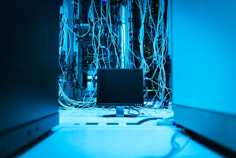
Photo by panumas nikhomkhai on Pexels
Different network devices operate at different layers of the OSI model, performing functions specific to that layer.
graph TD
    A["User Applications (Web Browser, Email)"] --> L7["OSI Layer 7: Application"]
    L7 --> L6["OSI Layer 6: Presentation"]
    L6 --> L5["OSI Layer 5: Session"]
    L5 --> L4["OSI Layer 4: Transport"]
    L4 --> L3["OSI Layer 3: Network"]
    L3 --> L2["OSI Layer 2: Data Link"]
    L2 --> L1["OSI Layer 1: Physical"]

    L7 --- D7["Gateway, Firewall"]
    L3 --- D3["Router"]
    L2 --- D2["Switch"]
    L1 --- D1["Hub, Repeater, Cable"]
- Layer 1 (Physical):
- Hub: Connects multiple devices in a network, simply repeating signals without inspecting data. It creates a single collision domain.
- Repeater: Extends network reach by regenerating signals.
- Cabling: The physical medium (Ethernet, fiber optic).
- Layer 2 (Data Link):
- Switch: Connects devices within a local area network (LAN). It learns MAC addresses and forwards frames only to the intended recipient, creating separate collision domains. It's much smarter than a hub.
- Bridge: Connects two LAN segments, forwarding traffic based on MAC addresses.
- Layer 3 (Network):
- Router: Connects different networks (e.g., your home network to the internet). It uses IP addresses to make routing decisions, determining the best path for data packets.
- Layer 4 (Transport):
- While not a distinct device category, advanced firewalls and some load balancers operate at this layer to manage TCP/UDP connections and session states.
- Layer 7 (Application):
- Gateway: Translates protocols between different network architectures.
- Layer 7 Firewall (Application Firewall): Filters traffic based on application-level data (e.g., blocking specific URLs or application content).
- Proxy Server: Acts as an intermediary for requests from clients seeking resources from other servers.
3. Worked Example
Imagine you're trying to send an email ("Hello, world!") from your computer (IP: 192.168.1.10) to a friend's computer (IP: 203.0.113.50).
- Application Layer (7): Your email client (e.g., Outlook) creates the email message.
- Presentation Layer (6): The email's text ("Hello, world!") is formatted into a standard character encoding like ASCII.
- Session Layer (5): A session is established between your email client and the email server to manage the ongoing email exchange.
- Transport Layer (4): The email message is broken into smaller segments. TCP adds sequence numbers and port numbers (e.g., port 25 for SMTP) to ensure reliable delivery and reassembly at the other end.
- Network Layer (3): Each segment becomes a packet. Your computer's IP address (192.168.1.10) is added as the source, and your friend's email server's IP address (e.g., 203.0.113.5) is added as the destination. Your router uses this destination IP to figure out the next hop on the internet.
- Data Link Layer (2): Each packet is encapsulated into a frame. Your computer's MAC address is added as the source, and the MAC address of your router (the next hop) is added as the destination. If your computer needs the router's MAC address, it uses ARP. Your switch within your home network will forward this frame to the router based on its MAC address.
- Physical Layer (1): The frame is converted into electrical signals (bits) and sent over your Ethernet cable to the router. The hub or repeater would just pass these bits along.
This process reverses on the recipient's side, with each layer processing its specific header/trailer information until the "Hello, world!" email is displayed in your friend's inbox.
4. Key Takeaways
- The OSI Model has seven layers, each with a distinct set of responsibilities.
- Higher layers (Application, Presentation, Session) deal with application-specific functions and data formatting.
- Lower layers (Network, Data Link, Physical) handle data transmission and network infrastructure.
- TCP/IP, the internet's protocol suite, maps roughly to the OSI model but is often discussed with four or five layers.
- Network devices operate at specific OSI layers; for instance, switches are Layer 2 and routers are Layer 3.
- Understanding the OSI Model helps you troubleshoot network issues by isolating problems to a specific layer.
Common Mistakes to Avoid:
- Don't confuse physical addresses (MAC, Layer 2) with logical addresses (IP, Layer 3).
- Don't think of the layers as completely isolated; they work together in a stack.
- Don't assume all network devices operate at only one layer; some advanced devices can function across multiple layers (e.g., Layer 3 switches).
- Don't forget that the application layer is where user interaction happens, not just network protocols.
5. Now Try It
Think about what happens when you load a webpage (e.g., www.example.com). Starting from your web browser, describe which OSI layers are involved and what general task each layer performs as your request travels from your computer to the web server and back. What kind of network device would be most critical at Layer 3 to get your request to the correct web server on the internet?
Success means you can clearly outline the role of at least 5 of the 7 OSI layers in this process and correctly identify the key Layer 3 device.
Frequently asked about OSI Model and Network Devices
Study this next
Get the full network + curriculum
Clone the complete plan to your dashboard for unlimited AI-generated notes, practice quizzes, and a personalised revision schedule.
Save this course free